A
MINUTE BRIEF ON ELECTROSTATIC GENERATOR
THEORY OF OPERATION:
Electrostatic generators
come in two categories: friction (triboelectric) and influence
(induction) machines. In both cases the generators convert
mechanical energy into electrical energy by separating electrical
charges and moving them against the electric forces to a collection
point where the charges are stored. The quantity of charges
separated and the amount of force it takes to keep them apart is
equivalent to the stored electrical energy (plus any losses).
TRIBOELECTRIFICATION:
Sliding across a car seat
with nylon pants on generates electricity by what is commonly called
friction. More accurately, the seat and pants are charged by
triboelectrification. When two different materials come into
intimate contact, the surface molecules of the materials share
electrons, that is, the motion of the electrons swarming around in
the molecules cross paths. Some materials have a stronger “hold”
on the electrons than others. When the two materials are pulled
apart, some of the electrons are trapped on the material that has the
stronger hold, giving both materials an equal charge in opposite
polarities. This charge is only on the surface of the materials and
usually, since the triboelectric materials are also insulators,
these charges are not free to move laterally on the surface.
FIGURE 1
The triboelectric
series is a grouping
of materials by their ability to hold excess electrons. A partial
listing from negative to positive (the most negative materials have
the strongest hold on electrons) is: silicone rubber, teflon, PVC,
polyethylene, synthetic rubber, brass, copper, paraffin, steel,
aluminum, wool, nylon, and glass. There are many circumstantial
factors that affect the triboelectric charging process: surface
roughness, humidity, and contamination just to name a few. Due to
the influence of these external factors, there may be instances when
the order listed may be violated (usually only where the two
materials are close together in the series though).
CHARGE BY INDUCTION:
An electrophorus is an
induction generator and will be used for illustrative purposes for
induction because of its simplicity. An electrophorus is a special
capacitor. What makes it special is its dielectric material, and its
removable capacitor plate. The dielectric material is an “electret”
or ferroelectric material with hysteresis. This material has
properties similar to its magnetic counterpart; magnets and
ferromagnetic materials. The electret will become “electrified”
(similar to magnetized) when placed in a strong electric field. This
is due to the electric dipoles in the material aligning themselves
with the applied electric field. Note that in this case, the effect
of the electrification is throughout the material. The dipoles are
"locked" into position by subatomic forces acting within
the material. The electric field will remain about the electret even
after the polarizing field is removed. If an electrically neutral
conducting plate is placed on either side of the electret and a wire
is then connected between them, charges will flow from one plate to
the other until the field created by the displaced charges reaches an
equilibrium with the field across the electret. Once the charges are
in balance, the wire connecting the two plates together can be
removed and the electrophorus looks no different than any other
capacitor charged up to a potential equal to the amount of charge
displaced by the electret’s intrinsic field.

Figure 2
The amount of charge
stored (or displaced) in a capacitor is measured in Coulombs and has
the following mathematical relationship with the capacitance and
voltage:
(equation A)
Q = C V
where: Q = charge in
Coulombs, C = capacitance in Farads, and V = potential in Volts
Also, the capacitor has
energy stored in it when charged. The energy relationship can be
expressed mathematically:
(equation B)
J = (V2
C)/2
where: J = energy in
Joules
Now if the removable
capacitor plate of the electrophorus is removed, the value of the
capacitor decreases inversely with the separation of the plates
(approximately). Also since the wire connecting the two plates was
removed (or the charging voltage source for a capacitor was removed),
the charges on the plates are trapped, and remain constant. If
equation A is rearranged, it can be seen that the voltage on the
capacitor goes up as the capacitance is decreased:
(equation C)
V’ = Q/(C - C)
where: C
= change in capacitance and V’ = new voltage across capacitor .
If the new voltage and
capacitance is substituted into equation B, it can be seen that the
energy stored in the resulting capacitor also went up:
(equation D) J’
= (Q/(C-C))2
(C - C)/2
= Q2 /{2(C -
C)}
where: J’ = new energy
stored in the capacitor
Of course the natural law
of conservation of energy says that you can't get something for
nothing (don't know why it is, it just is), so it must have taken
work to reduce the capacitance. This work is done by separating the
capacitor plates against the electrostatic force pulling them
together. Work can be defined in terms of applying a force through
a distance. This relationship can be expressed mathematically:
(equation E)
J = 1.356 F d
where: J = energy in
Joules, F = force in pounds, and d = distance in feet.
Essentially, induction
generators go about the process of generating static electricity by
repeatedly charging up a capacitor, separating the plates, and
“collecting” the charge off of the plates using a method
described below in the Van de Graaff generator, and discovered by
Michael Faraday in the early nineteenth century. The induction
generators with metallic plates have brushes that come in contact
with them when they are in the “inducing” electric field. This
allows the charges to flow between the capacitor plates to reach
equilibrium. As the plates are moved away from each other, the brush
contacts open up, trapping the charges on the plates. These plates
are moved against the electrostatic force to the collectors where
another brush makes contact with the charged plate and removes the
charges. Once the charges are removed, the plates no longer have a
force between them.
VAN DE GRAAFF
GENERATORS:
The Van de Graaff
generator was invented by Robert J. Van de Graaff in the 1930s (US
patent # 1,991,236). The VG1 is a Van de Graaff generator that
separates the charges by triboelectrification and then uses the
charged drive pulley to induce charges on the transport belt. The
drive pulley on the motor is made of teflon. It drives the rubber
transport belt which is in intimate contact with the pulley.
According to the triboelectric series, teflon is more negative than
rubber. This means that when the up going side of the rubber belt
separates from the teflon drive pulley, a net negative charge exists
on the teflon pulley and a positive one on the rubber belt in the
localized area of separation. Note that since both materials are
insulators, the charges are not free to move on the surface of them.
After the drive pulley has turned a few revolutions, it has a uniform
negative charge all around its circumference. The rubber belt
traveling up to the collector sphere has a positive charge on the
inside of surface of it (side contacting the drive pulley). It
travels up to the collector where the charges are removed as
explained later. When the belt comes down it is neutral (has the
charges on the inside removed).
A conductive brush with
many sharp points is placed on the opposite side of the rubber belt
where the negatively charged pulley and belt are in contact. The
sharp points allow the surrounding air to ionize easily in the
presence of an electric field. The brush has a wire connected to it
which connects to the inside of a metal hemispherical base cover.
Both this cover and the hollow collector sphere at the top of the Van
de Graaff generator behave in such a way that any charge that is
placed in it or taken away from it from the inside, will have an
immediate affect on the apparent total outside charge. That is, any
charge that is brought inside the sphere (or hemisphere) will
immediately be seen as adding to or subtracting from the total charge
on the outside of the sphere even though it still resides inside.
Another thing, if the charge that was brought inside is allowed to
come into contact with the inside of the conductive hollow sphere,
the charge will immediately be transferred to the outside, and no net
charge will then reside inside the sphere. This will be the case no
matter how great the charge outside the sphere or how small the
brought in charge was.
Now at the brush points
where the rubber belt and teflon are in contact, the teflon pulley
has a negative charge and the rubber belt is neutral (the inside of
the belt doesn't obtain the positive charge until the belt and pulley
separate further around the pulley, and the down going side is
neutralized prior to leaving the collector globe). The negative
charge on the pulley will cause electrons to be pushed off of the
brush points on the opposite side of the belt . When the field is
strong enough, electrons from the air molecules
in the vicinity of the brush jump off to the brush points, creating
positively ionized molecules. These molecules are free to move and
are attracted to the negatively charged pulley on the other side of
the belt. They move until they come into intimate contact with the
top side of the belt (since they cannot travel through it). They
become attached to the belt in a way similar to the attachment of the
triboelectric materials to each other, although these attachment
forces are not fully understood. Once attached, it requires a force
to separate the ions from the belt even after the field that caused
them to become attached is removed. It is this force that allows the
ions to remain attached to the belt while it is being moved up to the
collector, and it is this force that when exceeded will cause the
ions to detach and limit the amount of charge the generator can
output. The action is such that a net positive charge per unit
area will reside on the top side of the up going belt. The charges
are then moved up toward the collector sphere against the
electrostatic forces. They are brought inside the collector sphere,
and then are allowed to come in contact with the inside of the sphere
with the aid of a collector brush, at which time they are transferred
to the outside of the collector. The rubber belt is neutralized at
this point and then continues back out of the sphere carrying no
charge out with it. This process continues with the voltage building
up on the sphere by the addition of charge until breakdown occurs.
In the case of the VG1, that is around 70,000 volts.
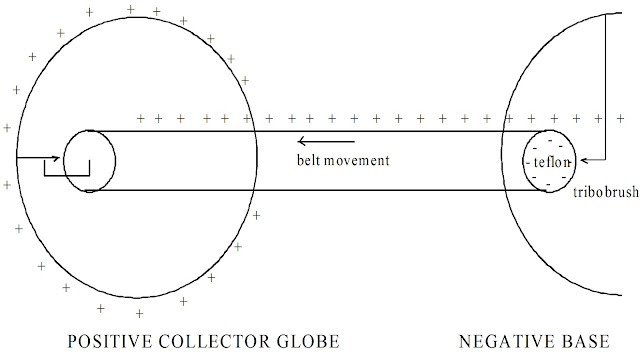
Figure 3
DISK INDUCTION
MACHINES:
The Wimshurst machine,
named after the British inventor James Wimshurst, is an induction
generator. It has two collectors, one positive and one negative, and
two counter rotating disks with metal sectors attached to them. The
sectors act as movable plates of a capacitor. In operation, an
electric field exists between the two collectors. Two of the sectors
which are displaced off the collector center line by some angular
distance, come into contact with a diagonal shorting bar (also
commonly called neutralizing bars). This bar connects the two plates
together electrically and causes charges to move from one plate to
the other while charging up the capacitance between each plate and
its respective collector. The same thing is happening to the sectors
on the counter rotating disk on the opposite side. As the disks
continue to rotate, the shorting bar brushes break contact and trap
the displaced charges on the sectors. These sectors are then rotated
away from the charged collector that induced the charge on them and
are forced to move (mechanical energy is converted to electrical
energy) toward the other collector which is charged in the same
polarity as the moving sector. When the charged sector reaches the
collector, a collector brush contacts it and transfers the charge in
a similar manner to the description given in the Van de Graaff
generator.

In a “plateless”
generator like the WM1, ions take the place of metallic plates.
Another difference in the WM1 is that it only has one rotating disk,
and it has separate inductor pole pieces instead of using the
collectors as the inductors. Other than this, the principal of
operation is the same as the Wimshurst machine. Ions from air
molecules (oxygen and nitrogen) are formed at the neutralizing combs
due to the high field strength induced by the field pole pieces on
the sharp edges of the combs. These ions are attracted toward the
disk by the pole pieces and get “stuck” on the disk similar to
the ions attaching to the Van de Graaff rubber belt. The disk
rotates around to the collector combs where the charged ions are
stripped off in a manner similar to the metal plate and Van de Graaff
generators, adding the charge to the collectors. As the charge
builds up on the collectors to a level higher than that on the field
pole pieces, the electric field between the probe rods and the
collector pole pieces causes ions to be formed at the probe rod tips.
The ions are mobile and can transfer more charge to the pole
pieces, increasing the field strength. This process continues until
an equilibrium is reached from leakage, corona, or breakdown.
Typically higher voltages
can be generated with a “plateless” generator than one with
plates. This is because the plates have edges and will cause the
field on the plate to be uneven. As the voltage on the plate
increases the higher field strength on the edges will ionize the air
around it and will carry off some of the charge on the plate. This
energy is then lost and winds up as chemical energy (ozone, etc.) or
is lost to heat.
Small Van de Graaff Generator in operation (video)
Induction Machine Operation (Video of Induction Machine)


